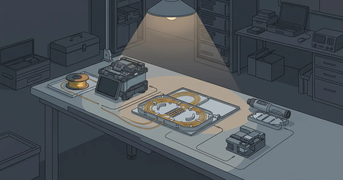
During November 2012, enterprise data centers and regional fiber backbones accelerating transitions toward 10 Gigabit Ethernet (10GbE) face persistent physical-layer instability on newly commissioned single-mode optical plant. Engineering teams often rely on simple red-light visual fault locators (VFLs) or basic broadband optical power meters to check dark fiber strands. Although simple continuity tests show light arriving at the far bulkhead, high-speed 10GBASE-LR (1310 nm) and 10GBASE-ER (1550 nm) links frequently drop frames or experience cyclical link-flap events. Optical fiber measurement literature underscores how splice loss, connector return loss, and tight bend radii govern single-mode transmission integrity. Why does an optical fiber path that passes a basic continuity light check still suffer intermittent bit-error bursts under 10GbE traffic?
What do bidirectional OTDR traces reveal about fusion splices and reflective connector pairs?
Single-mode optical fiber splice measurement studies demonstrate that Optical Time-Domain Reflectometer (OTDR) traces are subject to directional backscatter variations when joined fibers have slightly different mode-field diameters, making bidirectional trace averaging essential to determine true fusion splice loss. Experimental measurements of single-mode optical fiber macro-bending losses confirm that attenuation increases exponentially once bend curvature falls below critical radius thresholds, with 1550 nm wavelengths suffering substantially higher loss than 1310 nm wavelengths. Furthermore, optical fiber transmission investigations show that tight mechanical bending induces localized birefringence and polarization-dependent loss (PDL) in single-mode fibers, degrading signal margins across high-speed optical links. Field-installable optical connector studies establish that microscopic air gaps, end-face contamination, and poor polish geometry degrade Optical Return Loss (ORL), generating Fresnel back-reflections that destabilize high-speed laser transmitters. A continuous visible red laser or a simple one-way power meter reading only proves gross optical continuity across the core, completely masking high localized splice attenuation, dirty bulkhead reflections, and wavelength-specific macro-bends. OTDR instruments inject timed laser pulses at both 1310 nm and 1550 nm and measure Rayleigh backscatter and Fresnel reflections as a function of distance, localizing every fusion splice, mechanical joint, and patch-panel bulkhead along the span. Testing from only one end of a fiber span can produce a deceptive gainer, an apparent negative splice loss, whenever the launch fiber has a slightly larger Mode Field Diameter (MFD) than the receiving fiber, because the tighter downstream core scatters a higher fraction of light back toward the instrument. Only by capturing OTDR traces from both ends (A-to-B and B-to-A) using launch and receive test cables and averaging the directional readings can technicians verify that every fusion splice meets the stringent 0.1 dB to 0.3 dB loss budget required for multi-span 10GbE topologies. Simultaneously, reflective connector pairs with microscopic dust particles, skin oils, or air gaps generate severe Fresnel back-reflections. On 10.3125 Gbps serial links, multiple reflections between mated ferrule end-faces create interferometric intensity noise and destabilize Distributed Feedback (DFB) laser cavities, triggering intermittent cyclic redundancy check (CRC) error bursts despite an adequate average receive power reading.
How does macro-bending inside cramped patch drawers attenuate 1550nm and 1310nm wavelengths?
Cramped optical patch drawers and tight slack-storage loops subject standard single-mode fibers (ITU-T G.652.D) to severe macro-bending loss. The physical mechanism of macro-bending attenuation is strongly wavelength-dependent: the fundamental optical mode field at 1550 nm extends further into the surrounding glass cladding than at 1310 nm, meaning the outer tail of the 1550 nm wavefront radiates out of the core far more readily when the fiber curves sharply. When a technician forces a yellow single-mode patch cord or bare 250-micron buffer tube around a sharp cabinet corner below the standard 30-millimeter minimum bend radius, a 1310 nm continuity tester or 10GBASE-LR optic may show minimal added loss, while a 1550 nm 10GBASE-ER or DWDM wavelength suffers severe attenuation. Comparing 1310 nm and 1550 nm OTDR traces at the exact same distance event immediately exposes a physical bend: a true fusion splice exhibits nearly identical loss at both wavelengths, whereas a pinched splice tray or tight patch-panel bend shows a sharp attenuation spike at 1550 nm relative to 1310 nm. Tight mechanical bending and uneven clamping pressure inside overcrowded splice trays also induce stress birefringence in the silica core, causing polarization-dependent loss (PDL) that fluctuates as cabinet temperatures cycle. Enforcing physical bend-radius discipline requires routing all slack through 30 mm radius-limiting mandrels, using strain-relief boots on patch leads, and separating high-density fiber distribution frames from copper cabling trunks.
What inspection scope and launch-cable procedures guarantee clean optical handoffs at installation?
Ensuring zero-error 10GbE transport as of November 30, 2012, requires pairing bidirectional dual-wavelength (1310/1550 nm) OTDR certification with strict end-face inspection hygiene. Technicians must attach calibrated launch and receive reference cables so the OTDR dead zone does not obscure the first and last patch-panel bulkheads. Before mating any LC or SC ferrule, including factory patch cords, installers must inspect the end-face with a 400x video fiber microscope against IEC 61300-3-35 defect criteria and perform dry-reel cleaning until zero particulate contamination remains. Enforcing bidirectional OTDR verification, strict 30 mm bend-radius guides, and inspect-before-connect hygiene guarantees that enterprise optical infrastructure sustains bit-error rates below 10 to the minus 12 under full 10GbE production load.
Sources
- Institution of Engineering and Technology (IET): New simple one-end splice loss measurement method using an OTDR for single-mode optical fibre, 1986-05-08
- Optica Publishing Group: Measurement of optical fiber macrobending losses in a single turn with continuously-varying radius, 2009-03-22
- Wiley: Investigation of polarization-dependent loss for a macrobending loss sensitive single-mode fiber, 2009-06-01
- Optica Publishing Group: Low Return Loss Field-Installable Optical Connector, 2009-03-22